- 您现在的位置:买卖IC网 > Sheet目录345 > MT42L256M32D4KP-3 IT:A (Micron Technology Inc)IC LPDDR2 SDRAM 8GBIT 168FBGA
�� �
�
 �
�2Gb:� x16,� x32� Mobile� LPDDR2� SDRAM� S4�
�SELF� REFRESH� Operation�
�self� refresh� entry� is� registered;� however,� the� clock� must� be� restarted� and� stable� before�
�the� device� can� exit� SELF� REFRESH� operation.�
�Exiting� self� refresh� requires� a� series� of� commands.� First,� the� clock� must� be� stable� prior�
�to� CKE� returning� HIGH.� After� the� self� refresh� exit� is� registered,� a� minimum� delay,� at� least�
�equal� to� the� self� refresh� exit� interval� (� t� XSR),� must� be� satisfied� before� a� valid� command�
�can� be� issued� to� the� device.� This� provides� completion� time� for� any� internal� refresh� in�
�progress.� For� proper� operation,� CKE� must� remain� HIGH� throughout� t� XSR,� except� during�
�self� refresh� re-entry.� NOP� commands� must� be� registered� on� each� rising� clock� edge� dur-�
�ing� t� XSR.�
�Using� self� refresh� mode� introduces� the� possibility� that� an� internally� timed� refresh� event�
�could� be� missed� when� CKE� is� driven� HIGH� for� exit� from� self� refresh� mode.� Upon� exiting�
�self� refresh,� at� least� one� REFRESH� command� (one� all-bank� command� or� eight� per-bank�
�commands)� must� be� issued� before� issuing� a� subsequent� SELF� REFRESH� command.�
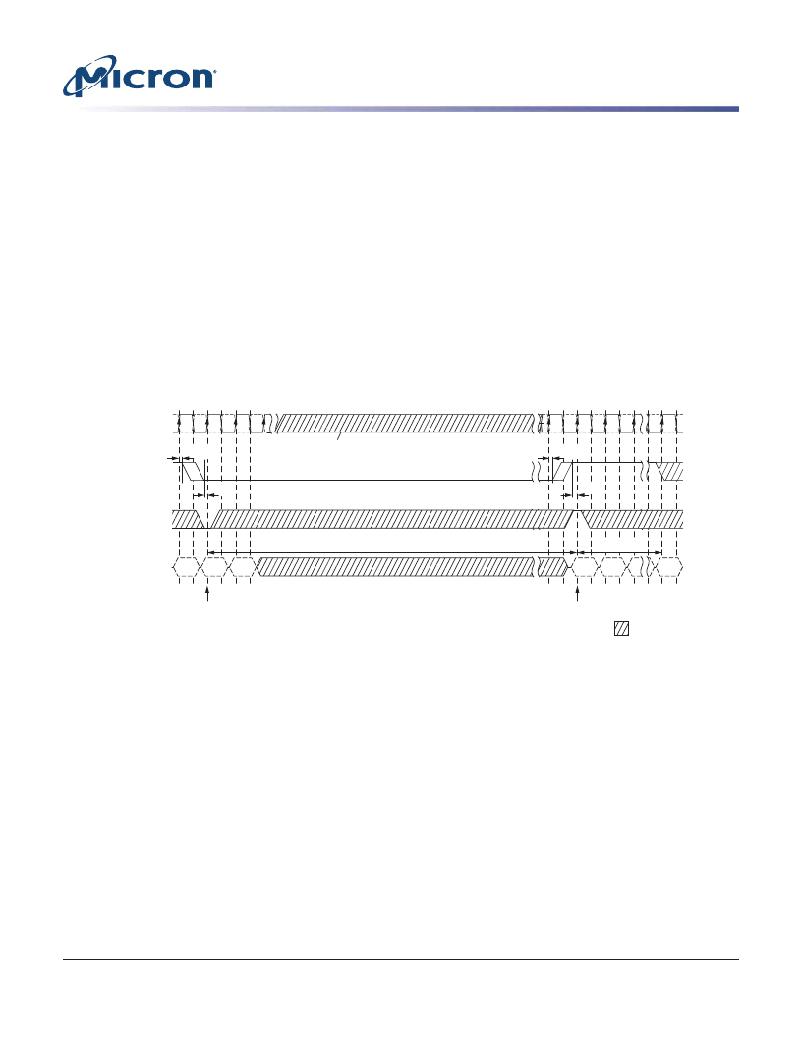
�Figure� 60:� SELF� REFRESH� Operation�
�CK/CK#�
�CKE�
�CS#�
�tIHCKE�
�tISCKE�
�Input� clock� frequency� can� be� changed�
�or� clock� can� be� stopped� during� self� refresh.�
�tCKESR� (MIN)�
�tIHCKE�
�tISCKE�
�tXSR� (MIN)�
�Valid� Enter� NOP�
�CMD�
�SR�
�Exit�
�SR�
�NOP� NOP� Valid�
�Enter� self� refresh� mode�
�Exit� self� refresh� mode�
�Don’t� Care�
�Notes:�
�1.� Input� clock� frequency� can� be� changed� or� stopped� during� self� refresh,� provided� that�
�upon� exiting� self-refresh,� a� minimum� of� two� cycles� of� stable� clocks� are� provided,� and� the�
�clock� frequency� is� between� the� minimum� and� maximum� frequencies� for� the� particular�
�speed� grade.�
�2.� The� device� must� be� in� the� all� banks� idle� state� prior� to� entering� self� refresh� mode.�
�3.� t� XSR� begins� at� the� rising� edge� of� the� clock� after� CKE� is� driven� HIGH.�
�4.� A� valid� command� can� be� issued� only� after� t� XSR� is� satisfied.� NOPs� must� be� issued� during�
�t� XSR.�
�Partial-Array� Self� Refresh� –� Bank� Masking�
�Devices� in� densities� of� 64Mb–512Mb� are� comprised� of� four� banks;� densities� of� 1Gb� and�
�higher� are� comprised� of� eight� banks.� Each� bank� can� be� configured� independently�
�whether� or� not� a� SELF� REFRESH� operation� will� occur� in� that� bank.� One� 8-bit� mode� reg-�
�ister� (accessible� via� the� MRW� command)� is� assigned� to� program� the� bank-masking� sta-�
�tus� of� each� bank� up� to� eight� banks.� For� bank� masking� bit� assignments,� see� the� MR16�
�PASR� Bank� Mask� (MA[7:0]� =� 010h)� and� MR16� Op-Code� Bit� Definitions� tables.�
�PDF:� 09005aef83f3f2eb�
�2gb_mobile_lpddr2_s4_g69a.pdf� –� Rev.� N� 3/12� EN�
�83�
�Micron� Technology,� Inc.� reserves� the� right� to� change� products� or� specifications� without� notice.�
�2010� Micron� Technology,� Inc.� All� rights� reserved.�
�发布紧急采购,3分钟左右您将得到回复。
相关PDF资料
MT45W1MW16BDGB-708 AT
IC PSRAM 16MBIT 104MHZ 54VFBGA
MT48H32M16LFB4-75B IT:C
IC SDRAM 512MB 54VFBGA
MT48H8M16LFB4-75 IT:K TR
IC SDRAM 128MBIT 133MHZ 54VFBGA
MTC100-JA2-P34
CONTACT INSERT PIN
MX841BE
IC CONVERTER WHITE LED 8-SOIC
MXHV9910BTR
IC LED DRIVER HIGH BRIGHT 8-SOIC
MXN12FB12F
MOTOR BRUSHED DC 12V 2922RPM
MXN13FB08B1
MOTOR BRUSHED DC 8V 4714RPM
相关代理商/技术参数
MT42L256M32D4KP-MS
制造商:Micron Technology Inc 功能描述:256MX32 LPDDR2 PLASTIC IND TEMP GREEN WFBGA 1.2V - Bulk